Continuing
on with Train 209 and Platform Wagons. Previous articles can be found as below.
The
next development in Platform Wagons came along in 1965 with the introduction of
the Commonwealth Engineering build QFX wagons.
Some QR documentation refer to this wagon as the PO class. Their entry
to service was around the time the RoA classification codes were be introduced.
Thus, the class became QFX, Q – Queensland, F – Flat, X – Bogie Exchangeable.
The wagons had drawhooks of Premium classification which later became known as
D2, and 18” self-contained buffers. Running Numbers 33008 – 33107. In the mid
70’s the wagons were fitted with auto couples, during the fitting period they
were classified QFXT. After all wagons were fitted with autos the class
reverted back to QFX.
The
wagon was 50 ft. long (3.3 metric units) and the hardwood deck that was 9 ft. 4
in. wide (The maximum limit of the rollingstock gauge). Two type of removable
stanchions could be fitted to the wagon, 8 ft. 7/8 in. between straight
stanchions and 8 ft. 10 ins. between set curved (goose neck) stanchions.
Stanchion pockets and lashing brackets/rings were every 5 ft. along the wagon
side, there was also 4 across each end. The wagon tare was approx. 18 T 5 C, and
carry on A & S Lines (15.75T Axle Load +) 43 T 15 C, some B Lines (12 Axle
Load) 29T 15C, on B Lines (10T Axle Load) 21T 15C. Cast steel QR 18 bogies,
with 5 ft. 6 in. wheel centres and 2 ft. 9½ in wheels was fitted to the wagon.
The drawing indicated the wagon can be fitted with standard gauge bogies.
The
big plus for these wagons was they were designed to carry their maximum load
supported symmetrically either solely at the headstock or concentrated near the
centre section of the wagon. Alternatively the maximum loading may be
concentrated symmetrically at other positions on the wagon. i.e. above the
bogies centres, or above the centre sill or above the various underframe cross
members provide their axle load was not exceeded. This makes the wagon very
suitable for heavy machine and end loading.


Photos Peter Kennedy
It
didn’t take long (67/68) before other jobs were found for the class, 4 wagons
(33017, 33035, 33059, 33085) were fitted with mounting plates for ISO
containers. Others followed as more
container traffic came available. The container mounts were at each end of the
wagon and when loaded with one container, the containers was to be loaded on
the hand brake end of the wagon. If the container was loaded on the other end,
the wagon would brake as a loaded wagon resulting in flat wheels.

QFX 33060, BK Runcorn.
QFX
33050 was used as a drum wagon for electrification.
Before
long before more were built, all came fitted for containers mounting plates and
were class QFC wagons. QFCA in 89 when buffers were removed.
1969 Nos 34424 – 34498 fitted with QR 27
bogies ComEng
1971/72 Nos 35660 – 35809 fitted with QR 18 A bogies Scotts of Ipswich
1973 Nos 36676 – 36725 fitted with QR 18 A
bogies Scotts of Ipswich
1975 Nos 37879 – 37953 fitted with QR 27 A
bogies Vickers Ruwolt
1975/76 Nos 38555 – 38654
fitted with QR 27 A bogies
Vickers Ruwolt


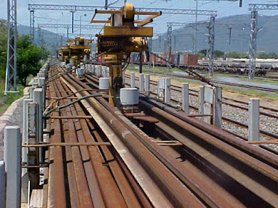
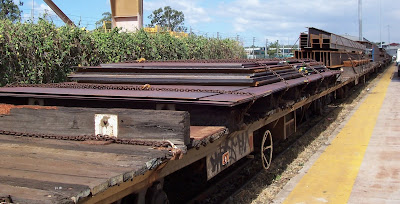
Various
modification continued for other traffic,
QR wagons in a set of
7 wagons for welded rail, 1 set in 1973 mostly QFX wagons (33041, 33061, 33062,
33053, 33079, 33084, 33097), 1983 two more sets were converted. The wagons were
for carrying 360 ft. (110 metre) welded rail (18 across by 3 high, subject to
rail size). 40 lengths of 60kg rail could be carried. Uncoupling rods removed
from intermediate ends. The wagons were red circle (80 Km/h freight) when
empty. The QR plan indicates a board painted yellow for lining up ends of rails
was painted across the end wagons. Also, wagons had 50 mm wide yellow band
painted full length of the solebar stencilled “Returned to Banyo Workshops when
unloaded. In later years the yellow band faded.


QFP
for Pozzolance Flyash Traffic, converted from QFXs 33008, 33025, 33037, 33056,
33057, 33058, 33060, 33083, 33096, 33098.

QPX 33057

QPC 38633 Cairns
QRG/QRGE
Rail Recovery Wagons, 2 sets of 7 wagons. W/N 1/86 (2-1-86) shows Rail Recovery
Gantry Train consists of 7 QRG wagons (33018, 33065, 34441, 35669, 35712,
35723, 38612), 1 QLP 37035 (ex QLX), and PRB 44997 (ex BLC) wagons will soon
entre service. This train consist will be responsible for the recovery, loading
and transport of discarded rail which has been replaced by new rail during
track laying operations.
The
QRG wagons, previously “QR” wagons (?? Numbers suggest a mix of QFX/QFC’s),
have been fitted with gantry support bearings, four fixed stanchions, and
electrical control equipment. The QLP wagons contains a power unit at one end
of the wagon and racks for storage of gantry components at the other end. The
PRB wagon is fitted with support brackets for carrying frames. Both sets were
still at Banyo in 2010, seven of the better wagons were transport by road to Rockhampton
Workshop for work wagons, the rest were transferred to Queensland Rail
ownership.


QFQ
Bulk Cement, most converted around 83/84. Converted from both QFX/C wagons.
8 wagons with 8 x 5 T
bins. (5 T bins were the same styles as SBC/WBC/HJC/FJC).
7 wagons with 4 x 10 T
cylinder type bins.
8 wagons with 2 x 10 T
cylinder type bins and 4 x 5 T standard bins.
4 wagons with 1 x 40 T
cylinder tank.


QFQ 35764 Cairns

QFQ 34496 Cairns
QFS
steel floor and suitable for motor vehicles.
Cross bars similar to SM/M series wagons were fitted.

QFCR
converted from QFX/QFC, fitted with electric feeder for powering refrigerated
containers. (1971). All wagons were fitted with auto couplings and bifurcated
train pipe (Brake pipe/cocks/hose bags both sides of the coupling).


Loading Containers on QFC wagons.


In recent times I have scratched build a number of QFC wagons. Materials used are listed below.
Construction

QFCS has 8 fixed spigots
welded mounted plates for 20 ft. containers.
(1967)

IRG/IRGE rail recovery wagons, 2 set of 7 wagons.


QFSR fitted with electric
feeder for powering refrigerated containers (steel deck). After the
introduction of the PRZY wagons some found their way onto other traffic
including the CD weight bridge train.

100 QC commenced entering
service in 1987, the timber deck was removed, container securing moved to load
container between the bogies. This increased the single container load to 27
tonnes. QFC position for a single container only allow 23 ton (A Class Lines). Removing the hardwood floor (4 tons) and
replacing it with a steel sheet increased the wagons carrying capacity.
W/N 10/89 (9-3-89) QFC to
QFCA and QC to QCA. A number of QFCA wagons are now in service, with the
buffers removed. QCA wagons will also be sent to traffic without buffers. When
all these wagons, with buffers removed, they will revert to their original QFC
and QC designations (?? Did they ??). These bufferless autocoupler wagon must not be coupled to drawhook wagons.
Steel pads are welded to the coupler to prevent the attachment of transition
couplings. W/N 13/89 (30-03-89) referred to QGX reclassed to QGA with the
removal of buffers.
QFC wagons had a high
floor above rail restricting the high of containers that could be carried, with
containers being build higher other classes of wagons were being introduced to
container traffic, by the mid 1990’s as new fleet of wagons were conveying
containers. The need for QFC dropped off. During their life many suffered
headstock corrosion/rust from carrying salted skins in containers. A number of
wagons had the end sections replaced during overhauls. Many were written off
due to rust issue once the new “B” and “P” series of container wagons entered
service.
PFO/PFU wagons were a
later conversion for steel traffic once released from container traffic by new
wagons in1997. QFX and QFC wagons had been used in this traffic all their life.
The PFO became captive to BHP traffic
and had bolsters add. Chains and dogs were used to secure the load. Tightening
chains with a dog can be accident waiting to happen, this was replaced by a
winch, positioning and size of the bolsters were altered to better suit long
lengths of steel overhanging the wagon resulting in the PFU wagon in 2000. These
wagons remained traffic to around 2008.

PFO


PFU with over
length loads


PFU with wide
plate loads


PFU with steel
loads

BMA wagon converted from
a QFC in 1999 was an ambulance wagon for mine emergences in the Coppabella
area. The wagon returned to Brisbane in 2009 and written off a few years later.
The wagons frames were
designed to carry more than 43T subject to suitable bogies being fitted and
track upgrading, with the NC Line upgrade to 20 axle load it was suggested but
didn’t come off. There was a plan to upgrade the wagon to 100 km/h running
(PFOY), but didn’t happen. The class served QR well and were the back bone of
heavy haul from the mid 60’s to about 2008. Only a few wagons of the class
remain today. Still in traffic are 2
sets of QR welded rail wagons, 1 set of IRG/E recovery rail wagons, IRD/IRDE
rail sets, QFRS wagons on the weight bridge train and a few QFC’s in
maintenance traffic. A number can be found in workshops as support vehicles (DUMP)
for moving jobs around the workshops.

Frame Detail.
Following on with the
QFX/C’s, Peter Kennedy has given me some details in regards to loading
prestressed concrete girders on QFX/C wagons. This will offer a something
different to model.
Perhaps I may enlarge slightly and that is the use of QFC
wagons for long prestressed concrete (PSC) girders. As PSC girders entered the world of bridge
construction they brought many advantages over steel in bridge building but
their transport brought far more problems than steel girders. The real strength
of PSC girders is in the heavy steel cables within the concrete. These
cables were highly stretched and provided the hidden strength. Because of the
stresses in the steel cable these girders must only be supported at or within
one metre of each end.
QFC wagons were 15.2 metres long so the max length of a PSC girder
could not exceed 17 metres in overall length on a QFC when the supports were
positioned at each end of the wagon. Obviously QR, was soon asked to convey
longer lengths. It appeared the only method was to mount swivel bolsters, one
on each of two QFCs. We had moved long logs in the past using swivel bolsters.
See General Appendix 1950 pages 211-215. These swivel bolsters were far simpler
than the sophisticated method required to move long and very fragile PSC
girders. While both bolsters obviously had to swivel on curves, one also
had to slide longitudinally so that when the train was reversed the draft gear
between the two QFCs compressed and one swivel slid along a flat slotted plate
to allow for this. The next problem was the twisting effect when the leading
wagon of the pair of carrying wagon entered the cant ramp at the beginning
of a curve and the following wagon was still level then a twisting reaction
would twist the girder and destroy the concrete. To overcome this one end of
the girder had to sit on a rocking base plate located within the swivel
bolster.
To secure the girders to the wagon the only place to chain
down the load was to chain the girder to the swivel bolster only to allow free
movement of the girder/s. We believed this was not sufficient as we carried
single girder up to 52 ton each or 3 girders at 21 ton each. To adequately
secure the girders vertical steel rods 1.5 inches in dia were screwed into the
swivel bolsters and a heavy timber placed atop the girder/s and bolted down
using the vertical rods. When more than one girder was carried on a pair of
swivelled bolsters on QFCs then each girder sat on its own rocker
plate. While “I” Beam PSC girders have a high level of strength vertically
they have little strength laterally and it was necessary to place some form of
lateral stiffing to overcome lateral deflection in transit in the form of a
timber or steel truss. Care had to be taken with the positioning of the swivel
bolsters on the QFC wagons to ensure that the bogie at either end of the
wagon were not overloaded. The amount of centre throw was also calculated to
ensure the outside edge of girder at the centre stayed within the width limits
for loading on sharp curves. To stay within the width and axleload limits of
very long girders a PE wagon was sometimes necessary placed between
the QFC’s as a runner. At the busiest times up to 9 sets of swivel
bolsters using 18 QFC wagons were in use, in slack times they were unbolted
from the QFCs and the wagons returned to normal traffic. The
conveyance of long PSC girders was planned conjointly by QR special loads
section, the Rollingstock design staff of the C.M.E branch and the PSC bridge
design Engineer from the Main roads Dept. and the makers of the early
girders, ‘’Dowstress’’ at Wacol. All this may be too much for some
readers but perhaps a challenge to the serious model maker to produce a model
of two QFC wagons fitted with the above described gear carrying a long large PSC
girder.


Photos; Peter Kennedy.
|
Year
|
Class
|
Numbers
|
Bogies
|
Notes
| |||||
|
1965
|
QFX
|
33008 - 33107
|
QR 18
|
P
266. As built D2 hook drawgear, later
to D1 with autos. QFXT for a period.
| |||||
|
33017
to QFC, photo shows 3 containers, must have had different mounting plates.
33012,
33020, 33077 frames for coil steel (1973)
33013
33018 QFX Bulk Cement.
Some
QFX wagons fitted with mounting plates & auto couplings classed QFC
(1967)
P 278
shows 33081, 33085, 33095 as QFC from P 266
P 362
shows 33008, 33025, 33037, 33056, 33057, 33058, 33060, 33083, 33096, 33098 to
QFP.
P 362A
shows 33028 to QFQ
P 462.
Shows
P 462 A
Shows 33043, 33735, 33039 as QFSR wagons.
Some
converted to QR rail sets. 33041, 33061, 33062, 33053, 33079, 33084, 33097.
Some
QFX fitted with 4 Pozzonlanic Cement bins QFP (1980)
Keith
Mc Drawing shows 3 mounting positions for 33017, 33081, 33095.
Keith
shows the following QFCR #’s 33072,
33015, 33032, 33014, 33090, 33074, 33047, 33042, 33052, 33105, 33070, 33099,
33107, 33035. The rest are 34… numbers.
33050
Drum Wagon
| |||||||||
|
1969
|
QFC
|
34424 - 34498
|
QR 27
|
P 278.
Page 2 allowable Configurations
Page
dated 96, includes QFC/QFCA/QFCR for “A” class lines
| |||||
|
1971 /72
|
QFC
|
35660 - 35809
|
QR 18 A
| ||||||
|
1973
|
QFC
|
36676 - 36725
|
QR 18 A
| ||||||
|
1975
|
QFC
|
37879 - 37953
|
QR 27 A
|
| |||||
|
1975/76
|
QFC
|
38555 – 38654
|
QR 27 A
|
| |||||
|
|
QFCR
|
|
|
P 295
(3/71) Converted from QFC/QFX for power containers
| |||||
|
1973
|
QR
|
|
|
P 318
(7/73)
| |||||
|
|
QFP
|
33008,
33025, 33037, 33056, 33057, 33058, 33060, 33083, 33096, 33098.
|
|
P 362
(4/80) Converted from QFX
4 x 10
t circular hopper bins.
| |||||
|
|
QFQ
|
1983
34485,
37903, 38581, 38593
1984 – 35731, 35782, 38607, 34464
|
|
P362 A.
(5/84) 8 x 5 t old style bins similar to FJC/SBC/HJSC etc.
Said to
be converted from QFX, but numbers indicate QFC’s.
| |||||
|
|
QFQ
|
34430,
34481, 34492, 35679, 35681, 35702, 35768.
33028
|
|
P 362 B
(9/84) ( 2 x 10 t & 4 x 5 t Bins)
Said to
be converted from QFX, but numbers indicate most are QFC’s.
1984
| |||||
|
|
QFQ
|
35661, 35662, 35670
|
|
P 362
C. (9/84)4 x 10 t circular hopper bins. P 362 B Said to be converted from
QFX, but numbers indicate most are QFC’s.1984 -
| |||||
|
|
QFQ
|
34496, 35748, 35758, 35764
|
|
P 362
D. (9/84) Single round tank. Said to be converted from QFX, but numbers indicate
most are QFC’s.
1984 –
| |||||
|
|
QFQ
|
34466, 38585, 38647
|
|
P 362
E.(5/87). 4 x 10 t circular hopper bins. 4 x 10 t circular hopper bins.
Bins
owner by Northern Certified Concrete 1984
| |||||
|
|
QCA
|
|
|
P 413
(2/88). Converted from QFC Wagons with buffers QC
P 412-2
Allowable Configurations
| |||||
|
|
QFS
|
1990 –
1991-
33037, 38565, 35701, 35793,
1992 – 38637, 35761, 36698, 34480, 38/579,
35689.
|
|
P 462
(6/91). Converted from QFC.
Container/Motor
Vehicle/Flat wagon.
| |||||
|
|
QFSR
|
34430, 33043, 33735 ??, 35806, 38649, 36709,
33039, 35670.
|
|
P 462
A. (11/97) Converted from QFC. Steel floor
Container/Motor
Vehicle/Flat wagon.
1993 –
| |||||
|
|
|
|
|
Ballast
Cleaning Machine
| |||||
|
|
QFCA
|
35761,
35798, 38649
|
|
Weighbridge
test train
| |||||
|
|
PFO
|
34431,
34433, 34442, 34452, 34494, 35672, 35694, 35720, 35734, 35753, 36687, 36699,
37936, 38628, 38652.
|
|
P 532
(1/99). Platform Wagon.
These
wagons reclassified from QFC to PFO when fitted with permanent dunnage and
securing equipment. (1998)
Some
wagons reclassified to PFU with permanent dunnage and chain winches
Bolster
on plan not the same as PFU’s
| |||||
|
|
PFU
|
33014,
33032,33036, 33042,33045, 33046, 33047, 33051, 33054, 33055, 33063, 33072,
33078, 33082, 34425, 34427, 34428, 34435, 34449, 34467, 34473, 34474, 36679,
36699, 37936
|
|
| |||||
|
|
PFOY
PFUY
|
|
|
P 532 A
((1/99) upgrade to 100 km/h (Wishful ??).
| |||||
|
|
IRD/IRDE
|
|
|
Rail
sets for QR. 14 wagons, 2 sets converted around 2010.
| |||||

Weighbridge Test Wagons.

Ballast
cleaning Machine


The 1979 Supplement to
Working Time Table showed the following restrictions for containers in the
South –Western Division.
The following conditions
apply to PYC, MTWC, QFC, QFCR, QFCS, PCS, and PCSS wagons loaded with 2.591 m
(8’ 6”) containers:-
(a) Trains conveying these wagons must not
travel via the platform road at Toowoomba and Dalby.
(b) Speed of trains conveying these wagons
must not exceed 15 km / h when crossing the Condamine River bridge at 254.640
km, Southern Line (Warwick).
(c) Speed of trains conveying these wagons
must not exceed 15 km / h when passing through the platform roads at Warwick
and Roma.
The 1982 Supplement to
Working Time Table showed the following containers on the network. There are
basically two lengths 6.1 m (20”0 and 12.2 m (40”0) with heights of 2.440 m
(8’), 2.650 m (8’ 6”) and 2.650 m (8’ 8½”). Only a few restrictions on 8’
containers, mainly not to travel between Brunswick and Roma Street via Central,
coal lines in CQ and west of Cairns must be on PC, PCS PYC or MTWC wagons.
8’ 6” containers had more
restrictions, Ipswich to Helidon on PC, B and PFCC wagons only, restrictions between
Helidon and Toowoomba. In the SWD on all lines, unless loaded on B, BR, PC,
PFC, and PFCF wagons and on PCS and PCSS wagons provided there is no sub frame
with restrictions. Central and Northern divisions much the same as 8’
containers.
The 8’ 8½” containers
were mainly interstate RACE containers. Travel in the Northern Division was the
same as the other containers. They were not permitted west of Ipswich. Restricted
mainly to the NCL line via Normanby.
The 1991 Supplement to
Working Time Table showed still only three heights of containers, 8’ 8½” high containers has expanded to
include SRC, QRCC, C.O.D, Q.R.X, TOTAL, R & H Transport, Nitropil, Rainbow
Furniture etc. The above containers can only be accepted between Helidon and
Toowoomba on B, PC, PFC, PFCF, PFCC, PJS, MPJS PCS and PCSS wagons with side
frames removed and with the written approval of the Regional Civil Engineer
Toowoomba.
Wagons carrying
containers must not be loose shunted.
Where practicable,
containers should be marshalled as closely as possible to the locomotive.
Between Helidon and
Toowoomba, speed of trains conveying containers must not exceed 15 km / h while
passing through Tunnel No. 3 at 144.500km, Tunnel No. 5 at 151.050 km and
Tunnel No. 6 at 151.900km. Suitable signs have been erected at these tunnels.
In the 1999 Operational
Route Manual only QCA wagons are shown with restrictions.
Westgate has a number of
QFX/C wagons.
The first 3 wagons are
Far North Hobbies Kits fitted with Steam Era wheels and bogies cut down for 12
mm operation. A first I had 2 wagons loaded with containers and 1 with army
APC’s. Various attempts were made to keep the wagon straight without any luck.
Currently the wagons have a square brass bar glued and screwed to the floor.
The load is build up around the bar hiding it from the viewer. So far so good,
the wagons often run at the front of the train without any trouble. The yellow
pipes are plastic balloon sticks, next time you are at Bunnings with the kids
and they are handing out balloons, grab a hand full of the sticks the balloons
are attached too. I also have some that are white. The runner load is made from
styrene sheet, rod and shapes.
When loading steel/pipes
etc, dunnage is placed between each row, today dunnage used is 4” x 4”
hardwood. The main reason being it is hard to put the wrong side down using
square timber. As each row is built up, the dunnage is place in the same
position for each row. I cut down match sticks for the dunnage and chocks each
side of the pipe. Securing equipment / chains etc. go over the load beside the
dunnage to make a tight unit. I used 40 links/inch scale chain to securing all
wagons. Not all chains go over all pipes, some have been belly wrapped. When
loading our wagon, keep the load within the loading gauge. DEL cab/QLX/ALY are
all good tools to gauge your load.


In recent times I have scratched build a number of QFC wagons. Materials used are listed below.
Floor:- Evergreen # 4067 Car Siding “0” scale 3¼”
spacing
.040
thick 32mm (9’ 4”) wide x 175 mm (50’)
long.
Sole Bar:- Mark out location of Sole bar, 4 mm
Outer
Edge:- Evergreen
# 102 .010’ x .040’ strip.
Wood
grain the floor, file, sand paper etc.
Remove stanchion/lashing ring
pockets. Approx. 1 plank wide x 1.5 mm deep.
Sole Bar:- Mark out location of Sole bar, 4 mm
Evergreen # 8420
(H0 10” x 4”) (.043” x .112”)
Angle edge Evergreen # 248
Quarter Round .060” (1.5mm). File
round side flat to form a triangle (optional).
Bogie Bolster:- 22.5 mm back from headstock
Evergreen
# 168. .080” x .188” (cut to fit between solo bars).
King
Casting:- Evergreen #
148 .040” x .188” (10 mm long and secured to the centre of the Bogie Bolster). Check bogie bolster height and add adjusted
material to have floor at correct height. (12.5 mm).

Evergreen
# 138 .030” x .188”
Mark Centre Line, drill with 1.5
mm drill, tap for a 2 mm screw.
Fix bolster to floor.

Centre
Sill:- Fix
Evergreen #167 .080” x .156” to floor
between bogie bolsters.
Sides formed from .040” sheet 9mm wide. Slop ends back 10’
(35 mm).
Fill with lead.
Enclose centre sill with .020 sheet cut to size, small
overhang.
Floor
Ribs:- Evergreen
# 8410 (H0 10” x 4”). Cut to fix between sole bar and centre sill. Only fix to
section between bodies in line with stanchion pockets. Fit the outer ends near
the bogies first, fill under floor with lead sheet. Fit rest of ribs to hold
lead into place. These will be at a reduced size to accommodate the thickness
of the lead used.

Add support each side of coupling on headstock


Coupler
Pocket:- I
scratch build the coupler box into the floor of the wagon as below. Have also
used Kadee # 262 coupler boxes screwed to the floor. This requires drilling
through the floor leaving a screw hole in the floor. OK if floor covered with a
load. OK for 20’ containers moulted on each end. I used 2mm nylon screws to fix
the coupling, easy to trim to floor level with a cutting blade.
Add support each side of coupling on headstock
Evergreen # 145 .040
x .100.

Scratch
built coupler box:-
Evergreen # 148 040” x
.188”. Pivot pin 5 mm back from
headstock. Add adjustment for correct coupler height.
Southern Rail bogies.
Evergreen # 138 .030” x .188” supports on headstock
Evergreen # 102 .010” x .040”
Back end plate Evergreen # 154 .060” x .080” Bottom Plate
Evergreen # 149 .040” x .250” Protrude about 1 mm beyond headstock, round
front. Top plate can also be extended beyond headstock and front rounded.
Pivot for coupling ⅛” brass
rod with 1 mm hole in centre.
Pivot mounting pin 1 mm brass
rod.
Making your own coupler box
you can reduce the coupling yoke restricting the side movement in the
coupler.


More on my method of fixing Kadee couplings to wagons can
be found on the Blog, March 2019. http://westgateswr.blogspot.com/2019/03/kadee-couplings-on-narrow-gauged-wagons.html
Headstock:- With 262 couplers. Evergreen # 118
.015 x .188 cut to size and shape. Fits each side of coupling box. Fill in
under coupler with Evergreen # 124 .020 x .080
3 mm
down each end, slopes back for 7 mm towards bottom of plate.
Evergreen # 8206 6’
x 2” support each side of coupling at the headstock ???
.4 mm holes for coupler lever
brackets.
Handbrake:- Evergreen # 144 .040 .080. Drops 4 mm
below floor. .012” brass rod
for wheel and release leaver. 25 mm of chain.
Spigot Plates:- .015 styrene. 4 mm x 7 mm . 4mm x 8.5 mm (middle) 1mm hole, 1 mm in.
Equipment Box:- .250 x.140 x 12 mm long. Side and Floor # 127 .156” x .020” .
020 x .040 Top of Box. Centre support .010 x .025
Number Board:- Evergreen # 127 .020 x .156. 18 mm long, corners cut off.
End Stanchion Pockets:-
Evergreen # 248 .06. Quarter round.
Coupler release levers:- .010
nickel silver wire. 20 mm long bent into required shape.
BP Hoses:- .025 Brass rod or Kerroby
Models HD 0037
Stanchions:- .030” x .030 11 mm, 1” x 4” each side.
The
following wagons still be completed with decals and weathering.

Stanchions are made to fit into the stanchion pockets on
the wagon and can be removed if not required.


Using older wagons as runners as I have done, restricts the
marshalling of the set. QFC have D1 drawgear and can be marshalled on the front
of a train. The P wagons used as runners have D4 drawgear and need to be
marshalled towards the rear of the train.

The load is also made removable to allow the wagons to
return empty for their next load. If I had attached the dunnage to the pipes
the wagon could have been used for other loads.
The pipe load is balloon sticks cut to length and glued to
fit within the loading gauge. This batch was white and were painted. The
securing straps is made from a plastic shopping bag, 1 mm strips are cut and
wrapped around the load at securing points on the wagon and glued.

All railway
networks have a limit on the size of loads that can be carried on their
networks. The loading gauge can vary from line to line subject to structures
etc. on the line. Without going into a long story, these days most networks
have two (2) loading gauges, a loose gauge for loose (pipes etc.) items loaded
on a wagon or container and a fixed gauge for containers. To assist me to keep
loads within gauge I have built gauge as in the photo. One end also has a gauge
for coupler height and position for marking buffers.

Container Loads


These wagons can be observed in traffic
on Westgate https://www.youtube.com/channel/UCJeqCUO7hR_qpv0ruPiMN_Q

Trust I have not missed something. Arthur.
Acknowledgments:
Various
QR/QRN documents and plans.
Peter Kennedy
Peter Kennedy
AMRA
Qld Library
Keith
McDonald
John
Armstrong