Sunday, 3 May 2020

Dream Operations.

A railway that runs well is a joy to operate. There will always be a few derailments due to operator error, pulling the wrong points etc. From time to time wagons will derail at one set location on the layout or another wagon will keep derailing on a set of points. All of this can be fixed to give trouble free operation of your layout.


 Another point to consider is if you run operations to a time table, derailments will cause all sorts of havoc across the operations session to the point where the session is out of control and may not be all that much fun.   
To have a railway that run well, their need to be a good interface between the wheel and the rail. Good track is a must, ask they say in the prototype you require a good top and line. In other words, the top of the track most be in line, no dips, no kinks, twists or holes. I can hearing many of you saying, branch lines are far from it. That’s true, speed is low, often low axle loads, and a big plus is the rollingstock has spring. Our models don’t have springs to ride out the up and downs, thus good track is a must. Time taken to make sure your track is good and in gauge will repay you many times over with good operations.
Modelling H0n3½ there are many issues that impact on that good wheel rail interface.
Over years they has been various track systems used along with endless wheelset manufactures.
 At first, Tri-ang TT3 equipment was used. The manufacture made both set track and rollingstock. Gem produced flex track and points, Peco had their Wonderful Wagon series, all British manufactures for 12 mm gauge.


In Europe there was Bemo (Fine and course systems) and Pilz, in later years we have Tillig and Peco pitching at the meter gauge modelling. (Approx. 11.9 mm gauge), Shinohara is H0n3½ track for the Japanese market (approx. 12.3 mm gauge), this track system is no longer available. Some track systems are code 83 rail, PECO is code 75 and Shinohara was code 70. In Europe there has been a number of manufactures of rollingstock, Berliner Bahnen, Roco to make a couple. On top of this some TT models were produced in the US for local modellers.

Gem Track and Points.
 
Shinohara Track and Points.
Bottom – Peco Code 75, Middle – Shinohara Code 70, Top – Gem Code 83 Track
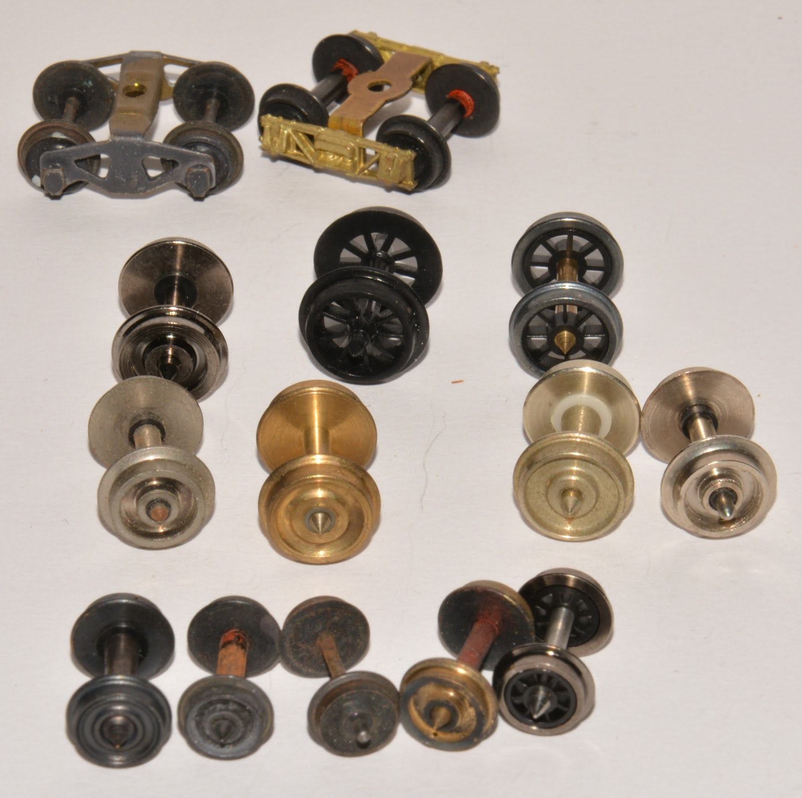
 Various manufactures have made wheelsets over the years, some plastic and other were metal of various types. Jackson, Wren, Peco TT, P.M.H, K&M made wheels for 12 mm and H0n3½ gauges, AR Kits, Steam Era Models. Now we have CGL, Caintode Flats Models, Southern Rail and Wuiske Models all producing wheelsets. Some wheelsets made for Shinohara track do not run through H0m points. Steam Era wheelset ran on most track systems I used over the years. The cost of them increased and troops stopped buying them. Production of 12 mm wheels no longer takes place, 9.5 mm disc wheels are still available. To add to this you will find the axle length will vary considerably between the manufactures. This prevents exchanging wheelsets between the various bogies.
 
When you look at the standards there is MOROP (European), NMRA, AMRA and British TT/TT3 or 3 mm. All are difference in various ways. I understand there was an H0n3½ standard developed in the 1960’s with AMRA and NMRA, but I was never aware of it. I started QR modelling in H0n3½ in 1973. At the time it was mainly British equipment used, some being Tri-ang. By today standards I fell the standard would not be that great anyhow. A paper written by Peter Knife “Modelling Australian HOn3½” for the Second Australian Narrow Gauge Convention held at Blackheath in 1998 cover standards and the industry at that time. http://www.minnipasiding.com.au/hon42.pdf
Today, in short we have track manufactures who do not make rollingstock and rollingstock manufactures who don’t make track.
I feel I cannot change track standards or any other standard for that natter, the most accessible track system today is the PECO H0m track which is the cheapest and most workable for the modeller. In recent year most manufactures producing rollingstock have adopted RP 25 contoured wheels. The theory is that the wheel is less likely to pick points and go around curves better. The standard states the wheels are best on track conforming to the limits of NMRA Standard S-3.2 and consistent with RP-10, RP-11 and RP-12.  At first we had RP 25/110 wheels, the tyre was wider than the prototype. To get a better looking wheel RP25/88 wheel was used.  The table below will give a overview of the difference between the two.
 
Tyre Width
Flange Width
Tread Width
Flange Depth
RP 25/110 wheel
.110”
(2.794 mm)
.030
(.762 mm)
.080
(2.032 mm)
.025
(.635 mm)
RP 25/88 wheel
.088”
(2.235 mm)
.025
(.635 mm)
.063
(1.6 mm)
.023
(.5842 mm)
 Yes, the RP25/88 wheel looks good, but you need a track system to the same standard. If the track is not the same standard, the wheels leave the rail and trend to fall into a hole at the vee on points. Some manufactures have back pedal a little and now use RP 25/99 wheels. Wider the wheel type, longer the axle, wider the bogie becomes. Wider bogies can take the true porotype look from the model.
This raises two questions, Question 1. Does my PECO H0m track conform to NMRA standards?. Track manufactures give you a gauge and not much more. The biggest issue is the clearances in the points around check rails. I’m aware some Peco track in other scales don’t meet these standards, my HO code 100 track has modifications to stop derailments. Question 2. How do RP25/88 wheelsets behave on the layout? Some run like a dream, faultless, can be pulled and pushed within in a string without any issues. Others turn into kangaroos at points, jumping up and down. Once a flange arrives on top of the rail, it’s any ones guess where the wheel will go, but mostly it finds the ballast. If the wagon is in a train being pulled, with a bit of luck at the next set of points the wheel will bounce back onto the rail. If you are pushing a wagon, once a flange arrives on top of the rail it all over. On closer inspection to find the cause, I observed there are differences in the flange shape on some wheelset said to be manufactured to the same standard. The back to back measurement could also very between different manufactures.
I have a test track, all wheelsets are tested before they hit the layout. The back to back is adjusted so the wheel run freely through the vee. Sitting on a chair, I place the board on the top of my legs, this allows me to alter the angle of the board and adjust the speed the wheels/bogies rolling through the points. Allowing the wheels to roll at a slow speed will show where the wheels meet resistance or climb onto the top of the rail head. 
Wheelsets that don’t run smoothly through the points have the back to back adjusted. I use two pullers to adjust the wheels on the axle.   
Hobby Tools Australia. This unit pulls the wheels out towards end of axle.
 
This gear puller can move the wheel in or out with adjustment of the centre screw. The centre screw was drilled out and a brass wheel bearing was inserted. I mainly use this tool for moving the wheel along the axle. I use the two to save adjusting the setting each time. (Lazy ??)
A good set of Vernier Callipers can be very helpful when adjusting wheelsets. The newer digital type make it much easier to read if you a bushie like me.  
 
 
Some wheels are gauged a recessed flange in the axle which prevents the wheels being pulled inwards. I’m very lucky I have a lathe, a small amount is taken off the back of the flange helps to achieve a wider back to back. I also do this with wheels with thicker flanges. Spinning a wheel in the lathe will also highlight if the wheel is square on the axle, I’m finding some insulated wheels have a wobble in them, thus they don’t run true and can pick the vee in the points at various times. Rolling the wheelset on a sheet of glass or a flat surface can achieve similar results. This could be the result of how you pull the wheelset out of the bogie, check before and pull on the non-insulated wheel. So be careful how you put the wheelset back into the bogie.  
 If you have plastic wheels there is nothing you can do to alter the back to back other than replacing the wheelset. Over a number of years, all my plastic wheels have been replaced with metal wheels. Don’t toss them in the bin, more on that down the track.  
 
The freer the wheels, the better with less friction. I have a modified H0 bearing tool to ream out the axle boxes on Delrin/Acetal plastic side frames.


The wheels need to turn freely will little to no side play in the axle.
The key point I try to achieve with wheelsets is reducing the resistance within the bogie and it interface with the track. Free rolling vehicles that run well on the track will give you less derailment and smoother operations overall. It will also show up how level your layout is.   
I try to have 30 foot wagons around 50 grams. Four wheeled wagons 25/30 grams appear to work OK, four wheeled wagons are trouble at the best of time if you want to push long strings. Some of the early carriage kits have a block of poxy for the roof, some are more than 3 times heavier than the rest of the kit, making the vehicle top heavy. I ream most of the poxy out using a dermal milling tool in a drill press.
 
Centre of gravity is very important to any railway, the lower the better. When adding weight to a vehicle I like to add plumber’s sheet lead to under the floor.
 
Coupled to this is the mounting position of the coupler. Most scratch build wagons I make my own coupler box reducing the side throw in the coupler. The back of the coupler socket is set level with the buffers heads. All wagons travel through cross overs without issues.
 Coupler heights can also differ, in the early days most kits were manufactured using the standard H0 Kadee coupler heights. This is higher than the QR  2’ 8” coupler height. To keep everything in prospective I mount couplers at 9.3 mm to the centre casting on the Kadee. Wuiske Models adopted a similar height for their RTR rollingstock. Southern Rail Models producing a dual position coupler box to cater for both by moving a spacer above or below the coupler shaft within the coupler box. For my money, wagons with standard H0 coupler height sit up much higher and makes the model look top heavy. As much as possible I try to keep the wagon/carriage floor and roof line at the correct height. The trip pin can hang low and catch on points etc., I bent them up a fraction. Australian Model Railway Magazine published an article “Coupling up in H0n3½” (April 2001). Stephen J. Colclough shares some hard earned lessons with coupling Queensland Railway HOn3½ models.
 
Building you own couple box into the wagon has some advantages, many older timber framed wagons have the bogie mounted on the end of the wagon. Standard Kadee coupler boxes fit between the wheels, but don’t allow them to swivel on small radius curves. Kadee makes a narrower # 262 box which can be purchased separate and are much better for the narrow gauge modeller. Building your own coupler box you can alter the shape of the yoke protruding out from the headstock. This can give extra support under the coupler shaft to prevent couples from sagging. It also allows you to reduce the cross movement within the box stopping couplings pushing outwards when pushing back.  
 

Most QR RTR rollingstock on the market today will run on PECO H0m track, radius of curves can be biggest issue, some locos may have issues on the points. If it is any comfort, the 6 wheeled DEL bogie caused many issues at first on the QR. I find PECO points can lose their gauge in the switch blades, I hold the toe of the switch hard up on the stock rail and with the other hand apply a small amount of pressure to the middle of the switch (curved closure rail), care is need not to apply to much pressure so that it pulls the rail out of the heel block.
 
 
Trust this helps you enjoy your railway more.
 
Arthur.


Friday, 10 April 2020

SBC Cement Wagon Kit


The SBC Cement Wagon Kit is available from Queensland Railway Miniatures via Facebook and at exhibitions. https://www.facebook.com/queenslandrailwaysminiatures.


Information on the prototype is on the header of the kit package.  The cement bins on the wagon were used on other QR wagons. FJC – 2 bins, HJC, WBC – 4 bins, WCC – 6 bins, QFQ – 8 bins. The bins are available from the manufacture as a separate item.

The clear plastic packet contains over 80 parts, each bin is made up of 18 parts. Opening of the packet is recommended on a clean clear work area as many of the parts are small and could be easily be lost. Some spares are in the kit.


More detailing parts were added after this photo.

Instructions for the bins is just under 5 pages, each step highlights preparation and assembly with a 3 D drawings. Prototype photos are included. 


The kit being reviewed was being developed at that time, the following additional items were required to the complete the kit. Bogies, couplers, trust rods, queen posts, screws for couplings, bogies and paint. Trust rods and queen post have now been included in the kit.  

The bins castings are crisp, some parts are sprue using flash which is used to support the part during preparation. Some small air bubbles were detected in the castings, once the kit was painted there present was less noticeable and didn’t distract the models. A small smear of super glue did fill most and provided an added weather appearance of spilled cement. All areas to be glued were lightly sanded with wet & dry. Following the steps in the instructions will give you a smart model of the prototype. I painted the bins with “Yellow Oxide” from a rattle can that was purchased from Auto Barn. The paint was sprayed into a plastic cup and applied to the model with an air brush. The paint is very thin and was applied in a number of coats to avoid the paint from running.     

The wagon consists of a moulded floor, underframe and a number of detailing parts. For the review kit there was no instructions at the time of assembly. The underframe is glued to the floor to form a platform wagon. The underframe is very well detailed, and reflects the 26 foot underframe drawing. The underside floor boards are shown.  Having the two parts separate is good, it allows you to drill and tap the coupling and bogies mounting holes without fear of drilling threw the top of the floor. The QR plan I have for the wagon is misleading and is different to the photo I have of the wagon. The plan shows a 1½ inch floor, the correct height of the sole bar on the plan is questionable. Most timber frame wagons have a 10 inch sole bar making the floor and sole bar around 12 inches.  The kit floor has individual boards which have a well-used weathered appearance. The top of the floor is a little uneven in parts and in some places the combined height of the floor when glued to the underframe is 4.5 mm.   


 Full brake gear is provided in the kit including brake pipe hoses and buffers for the headstock. I attached the bogies and couplings using 2 mm nylon screws. The coupler height was compatible with my other rollingstock (9.5 mm). I used Caintode Flats CFB3S 5’ diamond frame bogies. After a few days, the wagon did develop that unique timber frame wagon appearance of being push, pull and bashed around a shunting yard for several years.

The review wagon frame was painted “Engine Black”. Decals supplied in the kit are for the pre 1970 era (white), included were a wagon number, tare, carry and wagon length in imperial measure, all correct in fact and size. The floor was weathered by applying a couple of coats of light grey. The bins were glued to the floor and a spray coat of mud/dust was applied to all the completed model.  

 On the weight bridge the completed model comes in at 54 grams.   


This is the first kit for this manufacture and I’m sure it was a steep learning curve for a modeller new to the hobby. The wagon is packed with detail, looks like the prototype and is a very good representation of the prototype and will make a good addition to your wagon fleet.   

Congratulations Steve for having a go and for producing an awesome model, I look forward to other unique quirky wagons that make QR trains somewhat special that we come to love and like to see.    


SBC nd FJC on Westgate.  
 
Ipswich. The wagon has metric markings, mid 1970’s.  

 Arthur Hayes MMR.

 Since the review, the kit has been further refined and instructions have been finalised. Don’t look to hard at the underfloor detail on my model, I stuff it up (senior moment!!).  The wagon has been on the layout for a couple of weeks and has replaced my scratched build SBC wagon which form part of Shunt Train 656 featured in Operation for a Small Layout, Australian Model Railway Magazine Issue 322 February 2017

Page 1 of the 3 page instructions for the wagon is attached below.


Monday, 23 March 2020

QFX / QFC wagons


Continuing on with Train 209 and Platform Wagons. Previous articles can be found as below.  


The next development in Platform Wagons came along in 1965 with the introduction of the Commonwealth Engineering build QFX wagons.  Some QR documentation refer to this wagon as the PO class. Their entry to service was around the time the RoA classification codes were be introduced. Thus, the class became QFX, Q – Queensland, F – Flat, X – Bogie Exchangeable. The wagons had drawhooks of Premium classification which later became known as D2, and 18” self-contained buffers. Running Numbers 33008 – 33107. In the mid 70’s the wagons were fitted with auto couples, during the fitting period they were classified QFXT. After all wagons were fitted with autos the class reverted back to QFX.

The wagon was 50 ft. long (3.3 metric units) and the hardwood deck that was 9 ft. 4 in. wide (The maximum limit of the rollingstock gauge). Two type of removable stanchions could be fitted to the wagon, 8 ft. 7/8 in. between straight stanchions and 8 ft. 10 ins. between set curved (goose neck) stanchions. Stanchion pockets and lashing brackets/rings were every 5 ft. along the wagon side, there was also 4 across each end. The wagon tare was approx. 18 T 5 C, and carry on A & S Lines (15.75T Axle Load +) 43 T 15 C, some B Lines (12 Axle Load) 29T 15C, on B Lines (10T Axle Load) 21T 15C. Cast steel QR 18 bogies, with 5 ft. 6 in. wheel centres and 2 ft. 9½ in wheels was fitted to the wagon. The drawing indicated the wagon can be fitted with standard gauge bogies.

The big plus for these wagons was they were designed to carry their maximum load supported symmetrically either solely at the headstock or concentrated near the centre section of the wagon. Alternatively the maximum loading may be concentrated symmetrically at other positions on the wagon. i.e. above the bogies centres, or above the centre sill or above the various underframe cross members provide their axle load was not exceeded. This makes the wagon very suitable for heavy machine and end loading.


Photos Peter Kennedy
 
It didn’t take long (67/68) before other jobs were found for the class, 4 wagons (33017, 33035, 33059, 33085) were fitted with mounting plates for ISO containers.  Others followed as more container traffic came available. The container mounts were at each end of the wagon and when loaded with one container, the containers was to be loaded on the hand brake end of the wagon. If the container was loaded on the other end, the wagon would brake as a loaded wagon resulting in flat wheels.


QFX 33060, BK Runcorn.
QFX 33050 was used as a drum wagon for electrification.

Before long before more were built, all came fitted for containers mounting plates and were class QFC wagons. QFCA in 89 when buffers were removed.

1969       Nos 34424 – 34498 fitted with QR 27 bogies                  ComEng

1971/72  Nos 35660 – 35809 fitted with QR 18 A bogies               Scotts of Ipswich

1973       Nos 36676 – 36725 fitted with QR 18 A bogies               Scotts of Ipswich

1975      Nos 37879 – 37953 fitted with QR 27 A bogies                Vickers Ruwolt

1975/76 Nos 38555 – 38654 fitted with QR 27 A bogies                Vickers Ruwolt

 From a simple request for 10 wagons, 550 were built.


Various modification continued for other traffic,
QR wagons in a set of 7 wagons for welded rail, 1 set in 1973 mostly QFX wagons (33041, 33061, 33062, 33053, 33079, 33084, 33097), 1983 two more sets were converted. The wagons were for carrying 360 ft. (110 metre) welded rail (18 across by 3 high, subject to rail size). 40 lengths of 60kg rail could be carried. Uncoupling rods removed from intermediate ends. The wagons were red circle (80 Km/h freight) when empty. The QR plan indicates a board painted yellow for lining up ends of rails was painted across the end wagons. Also, wagons had 50 mm wide yellow band painted full length of the solebar stencilled “Returned to Banyo Workshops when unloaded. In later years the yellow band faded.


QFP for Pozzolance Flyash Traffic, converted from QFXs 33008, 33025, 33037, 33056, 33057, 33058, 33060, 33083, 33096, 33098.

QPX 33057
 
QPC 38633 Cairns 

QRG/QRGE Rail Recovery Wagons, 2 sets of 7 wagons. W/N 1/86 (2-1-86) shows Rail Recovery Gantry Train consists of 7 QRG wagons (33018, 33065, 34441, 35669, 35712, 35723, 38612), 1 QLP 37035 (ex QLX), and PRB 44997 (ex BLC) wagons will soon entre service. This train consist will be responsible for the recovery, loading and transport of discarded rail which has been replaced by new rail during track laying operations.

The QRG wagons, previously “QR” wagons (?? Numbers suggest a mix of QFX/QFC’s), have been fitted with gantry support bearings, four fixed stanchions, and electrical control equipment. The QLP wagons contains a power unit at one end of the wagon and racks for storage of gantry components at the other end. The PRB wagon is fitted with support brackets for carrying frames. Both sets were still at Banyo in 2010, seven of the better wagons were transport by road to Rockhampton Workshop for work wagons, the rest were transferred to Queensland Rail ownership.   


QFQ Bulk Cement, most converted around 83/84. Converted from both QFX/C wagons.

8 wagons with 8 x 5 T bins. (5 T bins were the same styles as SBC/WBC/HJC/FJC).

7 wagons with 4 x 10 T cylinder type bins.

8 wagons with 2 x 10 T cylinder type bins and 4 x 5 T standard bins.

4 wagons with 1 x 40 T cylinder tank.  


QFQ 35764 Cairns

QFQ 34496 Cairns

QFS steel floor and suitable for motor vehicles.  Cross bars similar to SM/M series wagons were fitted. 

 
 QFCR converted from QFX/QFC, fitted with electric feeder for powering refrigerated containers. (1971). All wagons were fitted with auto couplings and bifurcated train pipe (Brake pipe/cocks/hose bags both sides of the coupling).
 
QFCS has 8 fixed spigots welded mounted plates for 20 ft. containers.  (1967)


IRG/IRGE rail recovery wagons, 2 set of 7 wagons.


QFSR fitted with electric feeder for powering refrigerated containers (steel deck). After the introduction of the PRZY wagons some found their way onto other traffic including the CD weight bridge train. 
 
100 QC commenced entering service in 1987, the timber deck was removed, container securing moved to load container between the bogies. This increased the single container load to 27 tonnes. QFC position for a single container only allow 23 ton (A Class Lines).  Removing the hardwood floor (4 tons) and replacing it with a steel sheet increased the wagons carrying capacity.

W/N 10/89 (9-3-89) QFC to QFCA and QC to QCA. A number of QFCA wagons are now in service, with the buffers removed. QCA wagons will also be sent to traffic without buffers. When all these wagons, with buffers removed, they will revert to their original QFC and QC designations (?? Did they ??). These bufferless autocoupler wagon must not be coupled to drawhook wagons. Steel pads are welded to the coupler to prevent the attachment of transition couplings. W/N 13/89 (30-03-89) referred to QGX reclassed to QGA with the removal of buffers.   

QFC wagons had a high floor above rail restricting the high of containers that could be carried, with containers being build higher other classes of wagons were being introduced to container traffic, by the mid 1990’s as new fleet of wagons were conveying containers. The need for QFC dropped off. During their life many suffered headstock corrosion/rust from carrying salted skins in containers. A number of wagons had the end sections replaced during overhauls. Many were written off due to rust issue once the new “B” and “P” series of container wagons entered service.
PFO/PFU wagons were a later conversion for steel traffic once released from container traffic by new wagons in1997. QFX and QFC wagons had been used in this traffic all their life.  The PFO became captive to BHP traffic and had bolsters add. Chains and dogs were used to secure the load. Tightening chains with a dog can be accident waiting to happen, this was replaced by a winch, positioning and size of the bolsters were altered to better suit long lengths of steel overhanging the wagon resulting in the PFU wagon in 2000. These wagons remained traffic to around 2008.  
PFO


PFU with over length loads


PFU with wide plate loads


PFU with steel loads
 
BMA wagon converted from a QFC in 1999 was an ambulance wagon for mine emergences in the Coppabella area. The wagon returned to Brisbane in 2009 and written off a few years later.   
The wagons frames were designed to carry more than 43T subject to suitable bogies being fitted and track upgrading, with the NC Line upgrade to 20 axle load it was suggested but didn’t come off. There was a plan to upgrade the wagon to 100 km/h running (PFOY), but didn’t happen. The class served QR well and were the back bone of heavy haul from the mid 60’s to about 2008. Only a few wagons of the class remain today.   Still in traffic are 2 sets of QR welded rail wagons, 1 set of IRG/E recovery rail wagons, IRD/IRDE rail sets, QFRS wagons on the weight bridge train and a few QFC’s in maintenance traffic. A number can be found in workshops as support vehicles (DUMP) for moving jobs around the workshops.  
 

Frame Detail.


Following on with the QFX/C’s, Peter Kennedy has given me some details in regards to loading prestressed concrete girders on QFX/C wagons. This will offer a something different to model.    

Perhaps I may enlarge slightly and that is the use of QFC wagons for long prestressed concrete (PSC) girders.  As PSC girders entered the world of bridge construction they brought many advantages over steel in bridge building but their transport brought far more problems than steel girders. The real strength of PSC girders is in the heavy steel cables within the concrete. These cables were highly stretched and provided the hidden strength. Because of the stresses in the steel cable these girders must only be supported at or within one metre of each end. 

QFC wagons were 15.2 metres long so the max length of a PSC girder could not exceed 17 metres in overall length on a QFC when the supports were positioned at each end of the wagon. Obviously QR, was soon asked to convey longer lengths. It appeared the only method was to mount swivel bolsters, one on each of two QFCs. We had moved long logs in the past using swivel bolsters. See General Appendix 1950 pages 211-215. These swivel bolsters were far simpler than the sophisticated method required to move long and very fragile PSC girders.  While both bolsters obviously had to swivel on curves, one also had to slide longitudinally so that when the train was reversed the draft gear between the two QFCs compressed and one swivel slid along a flat slotted plate to allow for this. The next problem was the twisting effect when the leading wagon of the pair of carrying wagon entered the cant ramp at the beginning of a curve and the following wagon was still level then a twisting reaction would twist the girder and destroy the concrete. To overcome this one end of the girder had to sit on a rocking base plate located within the swivel bolster.                                          

To secure the girders to the wagon the only place to chain down the load was to chain the girder to the swivel bolster only to allow free movement of the girder/s. We believed this was not sufficient as we carried single girder up to 52 ton each or 3 girders at 21 ton each. To adequately secure the girders vertical steel rods 1.5 inches in dia were screwed into the swivel bolsters and a heavy timber placed atop the girder/s and bolted down using the vertical rods. When more than one girder was carried on a pair of swivelled bolsters on QFCs then each girder sat on its own rocker plate. While “I” Beam PSC girders have a high level of strength vertically they have little strength laterally and it was necessary to place some form of lateral stiffing to overcome lateral deflection in transit in the form of a timber or steel truss. Care had to be taken with the positioning of the swivel bolsters on the QFC wagons to ensure that the bogie at either end of the wagon were not overloaded. The amount of centre throw was also calculated to ensure the outside edge of girder at the centre stayed within the width limits for loading on sharp curves. To stay within the width and axleload limits of very long girders a PE wagon was sometimes necessary placed between the QFC’s as a runner.  At the busiest times up to 9 sets of swivel bolsters using 18 QFC wagons were in use, in slack times they were unbolted from the QFCs and the wagons returned to normal traffic.   The conveyance of long PSC girders was planned conjointly by QR special loads section, the Rollingstock design staff of the C.M.E branch and the PSC bridge design Engineer from the Main roads Dept. and the makers of the early girders, ‘’Dowstress’’ at Wacol. All this may be too much for some readers but perhaps a challenge to the serious model maker to produce a model of two QFC wagons fitted with the above described gear carrying a long large PSC girder.


Photos; Peter Kennedy.


Year

Class

Numbers

Bogies

Notes

1965

QFX

33008 - 33107

QR 18

P 266.  As built D2 hook drawgear, later to D1 with autos. QFXT for a period.

33017 to QFC, photo shows 3 containers, must have had different mounting plates.

33012, 33020, 33077 frames for coil steel (1973)

33013 33018 QFX Bulk Cement.

Some QFX wagons fitted with mounting plates & auto couplings classed QFC (1967)

P 278 shows 33081, 33085, 33095 as QFC from P 266

P 362 shows 33008, 33025, 33037, 33056, 33057, 33058, 33060, 33083, 33096, 33098 to QFP.

P 362A shows 33028 to QFQ

P 462. Shows 33043, 33050, 33037 as QFS wagons.

P 462 A Shows 33043, 33735, 33039 as QFSR wagons.

Some converted to QR rail sets. 33041, 33061, 33062, 33053, 33079, 33084, 33097.

Some QFX fitted with 4 Pozzonlanic Cement bins QFP (1980)  

Keith Mc Drawing shows 3 mounting positions for 33017, 33081, 33095.

Keith shows the following QFCR #’s 33072, 33015, 33032, 33014, 33090, 33074, 33047, 33042, 33052, 33105, 33070, 33099, 33107, 33035. The rest are 34… numbers. 

33050 Drum Wagon

1969

QFC

34424 - 34498

QR 27

P 278. Page 2 allowable Configurations

Page dated 96, includes QFC/QFCA/QFCR for “A” class lines 

1971 /72

QFC

35660 - 35809

QR 18 A

1973

QFC

36676 - 36725

QR 18 A

1975

QFC

37879 - 37953

QR 27 A


1975/76

QFC

38555 – 38654

QR 27 A


QFCR


P 295 (3/71) Converted from QFC/QFX for power containers

1973

QR


P 318 (7/73)


QFP

33008, 33025, 33037, 33056, 33057, 33058, 33060, 33083, 33096, 33098.


P 362 (4/80) Converted from QFX

4 x 10 t circular hopper bins.


QFQ

1983

34485, 37903, 38581, 38593

1984 – 35731, 35782, 38607, 34464


P362 A. (5/84) 8 x 5 t old style bins similar to FJC/SBC/HJSC etc.

Said to be converted from QFX, but numbers indicate QFC’s. 


QFQ

34430, 34481, 34492, 35679, 35681, 35702, 35768.

33028


P 362 B (9/84) ( 2 x 10 t & 4 x 5 t Bins)

Said to be converted from QFX, but numbers indicate most are QFC’s.

1984


QFQ

35661, 35662, 35670


P 362 C. (9/84)4 x 10 t circular hopper bins. P 362 B Said to be converted from QFX, but numbers indicate most are QFC’s.1984 -


QFQ

34496, 35748, 35758, 35764


P 362 D. (9/84) Single round tank. Said to be converted from QFX, but numbers indicate most are QFC’s.

1984 –


QFQ

34466, 38585, 38647


P 362 E.(5/87). 4 x 10 t circular hopper bins. 4 x 10 t circular hopper bins.

Bins owner by Northern Certified Concrete  1984


QCA


P 413 (2/88). Converted from QFC Wagons with buffers QC

P 412-2 Allowable Configurations


QFS

1990 – 34438

1991- 33037, 38565, 35701, 35793, 33043, 33050, 35704, 35798.

1992 – 38637, 35761, 36698, 34480, 38/579, 35689.


P 462 (6/91). Converted from QFC.

Container/Motor Vehicle/Flat wagon.


QFSR

34430, 33043, 33735 ??, 35806, 38649, 36709, 33039, 35670.


P 462 A. (11/97) Converted from QFC. Steel floor

Container/Motor Vehicle/Flat wagon.

1993 –


Ballast Cleaning Machine


QFCA

35761, 35798, 38649


Weighbridge test train


PFO

34431, 34433, 34442, 34452, 34494, 35672, 35694, 35720, 35734, 35753, 36687, 36699, 37936, 38628, 38652.


P 532 (1/99). Platform Wagon.

These wagons reclassified from QFC to PFO when fitted with permanent dunnage and securing equipment. (1998)

Some wagons reclassified to PFU with permanent dunnage and chain winches

Bolster on plan not the same as PFU’s 


PFU

33014, 33032,33036, 33042,33045, 33046, 33047, 33051, 33054, 33055, 33063, 33072, 33078, 33082, 34425, 34427, 34428, 34435, 34449, 34467, 34473, 34474, 36679, 36699, 37936


PFOY

PFUY


P 532 A ((1/99) upgrade to 100 km/h (Wishful ??).


IRD/IRDE


Rail sets for QR. 14 wagons, 2 sets converted around 2010.
 
Weighbridge Test Wagons.

Ballast cleaning Machine

Loading Containers on QFC wagons.


The 1979 Supplement to Working Time Table showed the following restrictions for containers in the South –Western Division.
The following conditions apply to PYC, MTWC, QFC, QFCR, QFCS, PCS, and PCSS wagons loaded with 2.591 m (8’ 6”) containers:-
(a)  Trains conveying these wagons must not travel via the platform road at Toowoomba and Dalby.
(b)  Speed of trains conveying these wagons must not exceed 15 km / h when crossing the Condamine River bridge at 254.640 km, Southern Line (Warwick).
(c)  Speed of trains conveying these wagons must not exceed 15 km / h when passing through the platform roads at Warwick and Roma. 
The 1982 Supplement to Working Time Table showed the following containers on the network. There are basically two lengths 6.1 m (20”0 and 12.2 m (40”0) with heights of 2.440 m (8’), 2.650 m (8’ 6”) and 2.650 m (8’ 8½”). Only a few restrictions on 8’ containers, mainly not to travel between Brunswick and Roma Street via Central, coal lines in CQ and west of Cairns must be on PC, PCS PYC or MTWC wagons.
8’ 6” containers had more restrictions, Ipswich to Helidon on PC, B and PFCC wagons only, restrictions between Helidon and Toowoomba. In the SWD on all lines, unless loaded on B, BR, PC, PFC, and PFCF wagons and on PCS and PCSS wagons provided there is no sub frame with restrictions. Central and Northern divisions much the same as 8’ containers.
The 8’ 8½” containers were mainly interstate RACE containers. Travel in the Northern Division was the same as the other containers. They were not permitted west of Ipswich. Restricted mainly to the NCL line via Normanby.
The 1991 Supplement to Working Time Table showed still only three heights of containers,   8’ 8½” high containers has expanded to include SRC, QRCC, C.O.D, Q.R.X, TOTAL, R & H Transport, Nitropil, Rainbow Furniture etc. The above containers can only be accepted between Helidon and Toowoomba on B, PC, PFC, PFCF, PFCC, PJS, MPJS PCS and PCSS wagons with side frames removed and with the written approval of the Regional Civil Engineer Toowoomba.
Wagons carrying containers must not be loose shunted.
Where practicable, containers should be marshalled as closely as possible to the locomotive.
Between Helidon and Toowoomba, speed of trains conveying containers must not exceed 15 km / h while passing through Tunnel No. 3 at 144.500km, Tunnel No. 5 at 151.050 km and Tunnel No. 6 at 151.900km. Suitable signs have been erected at these tunnels.    
In the 1999 Operational Route Manual only QCA wagons are shown with restrictions.
Westgate has a number of QFX/C wagons.  
The first 3 wagons are Far North Hobbies Kits fitted with Steam Era wheels and bogies cut down for 12 mm operation. A first I had 2 wagons loaded with containers and 1 with army APC’s. Various attempts were made to keep the wagon straight without any luck. Currently the wagons have a square brass bar glued and screwed to the floor. The load is build up around the bar hiding it from the viewer. So far so good, the wagons often run at the front of the train without any trouble. The yellow pipes are plastic balloon sticks, next time you are at Bunnings with the kids and they are handing out balloons, grab a hand full of the sticks the balloons are attached too. I also have some that are white. The runner load is made from styrene sheet, rod and shapes.
When loading steel/pipes etc, dunnage is placed between each row, today dunnage used is 4” x 4” hardwood. The main reason being it is hard to put the wrong side down using square timber. As each row is built up, the dunnage is place in the same position for each row. I cut down match sticks for the dunnage and chocks each side of the pipe. Securing equipment / chains etc. go over the load beside the dunnage to make a tight unit. I used 40 links/inch scale chain to securing all wagons. Not all chains go over all pipes, some have been belly wrapped. When loading our wagon, keep the load within the loading gauge. DEL cab/QLX/ALY are all good tools to gauge your load.


In recent times I have scratched build a number of QFC wagons. Materials used are listed below.
 
Construction 
Floor:-                        Evergreen # 4067 Car Siding “0” scale 3¼” spacing
                                    .040 thick    32mm (9’ 4”) wide x 175 mm (50’) long.
                                    Wood grain the floor, file, sand paper etc.

Remove stanchion/lashing ring pockets. Approx. 1 plank wide x 1.5 mm deep.
 
Sole Bar:-                 Mark out location of Sole bar, 4 mm
Evergreen  # 8420  (H0 10” x 4”) (.043” x .112”)
Angle edge Evergreen # 248 Quarter Round .060” (1.5mm).      File round side flat to form a triangle (optional).
Outer Edge:-            Evergreen # 102 .010’ x .040’ strip.
Bogie Bolster:-        22.5 mm back from headstock

Evergreen # 168.  .080” x .188”   (cut to fit between solo bars).

King Casting:-         Evergreen # 148 .040” x .188” (10 mm long and secured to the centre of the  Bogie Bolster).  Check bogie bolster height and add adjusted material to have floor at correct height. (12.5 mm).
                                    Evergreen # 138   .030” x .188”   
                                    Mark Centre Line, drill with 1.5 mm drill, tap for a 2 mm screw.   
Fix bolster to floor.


Centre Sill:-              Fix Evergreen  #167 .080” x .156” to floor between bogie bolsters.
Sides formed from .040” sheet 9mm wide. Slop ends back 10’ (35 mm).
Fill with lead.
Enclose centre sill with .020 sheet cut to size, small overhang.
Floor Ribs:-              Evergreen # 8410 (H0 10” x 4”). Cut to fix between sole bar and centre sill. Only fix to section between bodies in line with stanchion pockets. Fit the outer ends near the bogies first, fill under floor with lead sheet. Fit rest of ribs to hold lead into place. These will be at a reduced size to accommodate the thickness of the lead used. 

Coupler Pocket:-   I scratch build the coupler box into the floor of the wagon as below. Have also used Kadee # 262 coupler boxes screwed to the floor. This requires drilling through the floor leaving a screw hole in the floor. OK if floor covered with a load. OK for 20’ containers moulted on each end. I used 2mm nylon screws to fix the coupling, easy to trim to floor level with a cutting blade. 

                                    Add support each side of coupling on headstock
Evergreen # 145  .040 x .100.
 
Scratch built coupler box:-

Evergreen # 148 040” x .188”.  Pivot pin 5 mm back from headstock. Add adjustment for correct coupler height.

Southern Rail bogies. Evergreen # 138  .030” x .188”                  supports on headstock Evergreen # 102 .010” x .040”           Back end plate Evergreen # 154 .060” x .080”                            Bottom Plate Evergreen # 149 .040” x .250” Protrude about 1 mm beyond headstock, round front. Top plate can also be extended beyond headstock and front rounded. 
Pivot for coupling ⅛” brass rod with 1 mm hole in centre.

Pivot mounting pin 1 mm brass rod. 

Making your own coupler box you can reduce the coupling yoke restricting the side movement in the coupler.  


More on my method of fixing Kadee couplings to wagons can be found on the Blog, March 2019.   http://westgateswr.blogspot.com/2019/03/kadee-couplings-on-narrow-gauged-wagons.html

Headstock:-             With 262 couplers. Evergreen # 118 .015 x .188 cut to size and shape. Fits each side of coupling box. Fill in under coupler with Evergreen # 124 .020 x .080
                                    3 mm down each end, slopes back for 7 mm towards bottom of plate.
Evergreen # 8206  6’ x 2” support each side of coupling at the headstock    ???

.4 mm holes for coupler lever brackets.

Handbrake:-             Evergreen # 144 .040 .080. Drops 4 mm below floor.            .012” brass rod for wheel and release leaver. 25 mm of chain.  

Spigot Plates:-        .015 styrene.  4 mm x 7 mm . 4mm x 8.5 mm (middle)           1mm hole, 1 mm in.

Equipment Box:-   .250 x.140 x 12 mm long.     Side and Floor # 127 .156” x .020”  .

020 x .040 Top of Box. Centre support .010 x .025

Number Board:-          Evergreen # 127  .020 x .156. 18 mm long, corners cut off.

End Stanchion Pockets:- Evergreen # 248 .06. Quarter round.

Coupler release levers:- .010 nickel silver wire. 20 mm long bent into required shape.

BP Hoses:-                   .025 Brass rod or Kerroby Models HD 0037

Stanchions:-                .030” x .030   11 mm, 1” x 4” each side.    

The following wagons still be completed with decals and weathering.


Stanchions are made to fit into the stanchion pockets on the wagon and can be removed if not required.
 
 
Using older wagons as runners as I have done, restricts the marshalling of the set. QFC have D1 drawgear and can be marshalled on the front of a train. The P wagons used as runners have D4 drawgear and need to be marshalled towards the rear of the train.   
 

The load is also made removable to allow the wagons to return empty for their next load. If I had attached the dunnage to the pipes the wagon could have been used for other loads.
The pipe load is balloon sticks cut to length and glued to fit within the loading gauge. This batch was white and were painted. The securing straps is made from a plastic shopping bag, 1 mm strips are cut and wrapped around the load at securing points on the wagon and glued.  


All railway networks have a limit on the size of loads that can be carried on their networks. The loading gauge can vary from line to line subject to structures etc. on the line. Without going into a long story, these days most networks have two (2) loading gauges, a loose gauge for loose (pipes etc.) items loaded on a wagon or container and a fixed gauge for containers. To assist me to keep loads within gauge I have built gauge as in the photo. One end also has a gauge for coupler height and position for marking buffers.   
 
Container Loads


These wagons can be observed in traffic on Westgate https://www.youtube.com/channel/UCJeqCUO7hR_qpv0ruPiMN_Q


Trust I have not missed something.   Arthur.
Acknowledgments:

Various QR/QRN documents and plans.

Peter Kennedy
AMRA Qld Library
Keith McDonald
John Armstrong