Sunday, 12 July 2020

Dining Cars


Dining Cars provided seated meals (Breakfast, Lunch and Dinner) on selected sectors on our trunk Mail Trains from around 1930 to 1970. Railway Refreshment Rooms (RRR) at various stations would provide light meals in the form of sandwiches, pies, drinks etc. Some at larger locations provided sit down meals for sectors not covered by the dining cars.

Passengers requiring a cup of tea and a pie need to wait for these stations as well. Plus, many of these RRR had bars attached. In 1969 I worked Homestead (Mt Isa line, 73 Km’s west of Charter Towers) which had a RRR, the manager lived on site with her quarters included. It was privately run and I know a cup of tea and a pie was not on the menu. When I arrived soft drinks were added to the menu. Mixed trains heading west, about one a day would stop for refreshments. It was more a the local watering hole, most night around 10 o’clock you would be picking up the locals that went base over apex over the signal wires. Most were not in a condition to be able to return to their feet without assistance.   

RRR managers a couple of hours before the due arrival of a train required train information, expected time of arrival and the train CANA. CANA was in the telegraph code was for number of passengers on the train. Hot drinks were served in china cups, the passenger would pay a deposit and be given a ticket which allowed the passenger to take the cup onto the train. At the next RRR the passenger could return the cup with the ticket and receive a refund. If a train was running late, the time at the station was reduced.        


As I read notes/books from various historians the operation of dining cars varies a bit about where they was added to or taken off trains, may be different periods with different timetables. Looking at the Western Mail (Train 8S) in the 1939 Main Line Timetable, the train departing Brisbane Central at 3:15 pm. Toowoomba 7:20/40 pm as the dinner stop in the RRR and refreshment, Dalby 9:25/35, Chinchilla 11:15/30, Miles 12:32/42 am, Roma 4:02/17. Mitchell 6:36/56 attach Dining Car, Charleville 12:18 pm. Breakfast and an early Lunch were the meals provided. The train continued to Cunnamulla on Saturday only. On the return train 13 down Western Mail departed Charleville at 3:02 pm, Mitchell 8:21/41pm, refreshment and detach dining car. Roma 11:04/14 pm, Toowoomba 7:40/8:00 for breakfast in the RRR, arriving Brisbane 11:57 am. The 1948 timetable was much the same.

The 1958 timetable showed the Westlander being worked by a diesel electric locomotive leaving Brisbane a few hours later at 6:55 pm. Refreshments Toowoomba 11:01/25 pm, Dalby 1:17/25 am. Roma 6:59/7:35 change locomotives and attach dining car. Charleville 3:17/52.  The train was due to arrive at Cunnamulla 9:37 pm, this sector was worked with a PB15 engine with WW water wagon attached, a total of 10 vehicles. The train was at Wyandra 6:37/57 pm giving passenger plenty of time to duck over to the pub for something to eat and drink. The dining car providing breakfast, lunch and dinner on the Roma – Cunnamulla sector. In later years the dining car staff left the train in Charleville and stayed in quarter until the return of the train the next day. On the return the train left Charleville at 3:50 pm, Roma 11:30/58 pm, detached dining car and change locomotives. Toowoomba was the breakfast stop 7:40/8:05 pm, arriving in Brisbane at 12:00 midday.  Dining car staff also assist in the RRR prior to the arrival of the train.

On the Sunlander the dining car was on the train between Bundaberg and Mackay, providing Breakfast, Lunch and Dinner. At the time northbound Sunlander (241) departed Roma St (Brisbane) at 9:30 pm, Bundaberg 5:33/6:00, attach Dining Car, refreshments, Rockhampton 12:05/45, refreshments. St Lawrence 4:37/47 refreshments, Mackay 8:06/36 pm, detach dining car and refreshments. Southbound Sunlander (266), Mackay 5:47/6:18 am attach dining car and refreshments, St Lawrence 9:42/52, refreshments, Rockhampton 1:30/2:05 refreshments, Bundaberg 8:26/9:00 pm, detach dining car. Roma Street (Brisbane) 6:00 am. Dining car staff would swap when the north and south bound train crossed each other. From what I recall, there was a staff of five required to work the dining car. Meals were provided in seating, the night before the Conductors would hand out meal sitting tickets. First class passengers received first pick at available times. During holiday periods three seating was not uncommon.

1967 I was at Mackay working as a fireman for the sugar season, from time to time you would be rostered on the station shunt. Afternoon shift would take the dining car off the Sunlander and the night shift would attach it to the train with the PB15 shunt engine. I recall one morning the dining car was pulled from the shed without the shore power being disconnected.  We also worked the main line trains to St Lawrence, regularly I would be rostered 266 (southbound Sunlander) on duty 5:15 am to St Lawrence, arrive 9:42 am return 241 (north bound Sunlander) on duty 4:17 pm, arrive Mackay 8:06 pm, it was an awesome job, both of us would wear a white shirt for the day. It would set you up for a day job the next day, generally a 12 hour branch job. An added bonus was it was counted as two shift, after completing 10 shifts within the fortnight it was class as overtime. Other guys in the quarters indicated I was paying the roster clerk.

Dining cars at their depot station were hooked to shore power. A special siding with a shed was provided at one of the station near the RRR. Dining car provided a bit of work for the station/yard shunters. At some stage the dining cars were turned before there next trip. After each trip the food left over would be taken back to the RRR and likewise would need to be loaded up before the next trip. The kitchen end would be the best end to have on the stop blocks for loading and unloading. At Roma the dining car siding was on the western end of the station. I’m having trouble recalling if the kitchen was the leading end of the carriage, I was always on the train, and I can only assume what happened before the arrival of the Westlander. The dining car was attached to the train between cars 3 and 5. Cars 1, 2 and 3 were first class carriages and cars 5, 6, 7 and 8 were second class carriages. The dining car was car 4.To reduce the number of moves with the leading portion of the train still containing passenger the shunt engine would push the dining car out onto the leading part of the train with train brakes applied.   


The following moves would be required.
Prior to the arrival of the Westlander, the shunt engine would pick up the dining car from the siding.
One of two things would be required, turn the dining car on the angle or run around the dining car. Running around vehicle is going to the other end, in this case the dining is on the Brisbane eastern end of the shunt engine coming out of the siding and needs to be on the western end. 
Wait the arrival of the train in a siding with access to the main line.
With the Westlander stopped on the platform with the guards van on the platform, the incoming DEL would come off the train to go the shed.
Two C17 locomotives attached would be shunted to the lead of the train. During these moves, passengers would be leaving the train heading for the refreshment rooms for a cuppa and something for breakfast if you were not going to the dining car after departing.
The train’s power car attendants would disconnect the power cables supplying A/C power to the train between cars 3 and 5. The shunter would uncouple the leading section of the train, the train engine would pull ahead clear of the loop points,
Shunt engine would push the dining car onto the leading section of the train and return to the siding.
The lead section of the train would push back on the carriages on the platform, couple up and hook up A/C power supply. A train safety test would follow before departure. 37 minutes was allocated for the work.

Much the same occurred detaching the dining car, the shunt engine would be attached to the dining car after the train had be parted. After the train departed, the shunt engine would place the dining car in it’s the siding.

In 1970 all dining cars were converted to Griddle Cars which provided both meals and refreshments reducing the time required at stations, these cars were on the train for the entire journey. Food Bar Cars were converted from first class seating cars for the western trains allowing the converted dining cars to work the Sunlander services.

The plan book does not show many Dining Cars, prior to the arrival of the Sunshine Cars, most appear to be conversions from other carriages. All up three Sunshine Express Dining Car were built, two (1255/1256) were built with first batch of cars and a third (1376) with the second series. Carriage 1376 was similar to other two carriages except windows in the kitchen end of the carriage. Car 1255 is in the current heritage fleet, Car 1256 became part of a Cooroy Restaurant in the butter factory siding and car 1376 was converted to a CW 74 camp wagon in April 1965.


In 1970, cars 1255 and 1256 were converted to Griddle Car. The kitchen area was extended to make a servery, gas bottles were added reducing seating from 30 to 22. These wooden cars were used on special trains that ran and second division of mail trains running during holiday periods.    


My model is a carriage from the first batch and is a 3 foot 6 model kit. During construction the only photos I had was of 1255 as a Griddle Car. Some features of the carriage were questionable as a dining car. As per Norn, when finished you find the answers you were looking for, I located a John Armstrong photo of the carriage 1256 in 1964. My educated guess turned out to be correct.


The carriage body was painted with PGC “QR Passenger RED” lacquer paint. The dining area was scratch build for styrene, very simple construction as only the top of the tables are visible. Seating was much the same, just blocks with backs made of styrene. The figures were given to me by Ken, an eBay purchase for a few dollars. I think the scale could be 1:100. The pack contained about 100 figures, with many repeats and not much detail. That would be OK given they were inside a carriage. The figures were hand painted with Model Colors. I find a drop of paint goes a long way and dries within a few minutes. The two cooks in the kitchen and the two waitress were Preiser figures.


From time to time some carriages had white wall types on the wheels, I don’t think it lasted all that long, one of the Griddle Car photos shows the carriage with them. To give the carriage a smart look I added them with the view if I don’t like it I can repaint them black.   


From above you can see that you can have some operations with your mail trains by having a dining car on your layout. I’m using the dock platform as the dining car siding during the running of my second 13 down, in other words “second division of the Westlander”.


 The 1970 Supplement to Working Time Tables shows a 1720 locomotive can haul 510 tons on a passenger train consisting of ordinary carriages from Charleville to Brisbane. The maximum of vehicles must not exceed 15. The same locomotive can haul 370 tons between Murphy’s Creek and Toowoomba in the UP direction heading west, that about 12 carriages.  

My second division of 13 down is marshalled similar to the Westlander.
Loco, AL first class seating car, 2 DAS first class sleeping cars, dining car, 2 FBS second class sleeping cars, 3 BL second class seating cars, baggage car and mail van.  

In the 1960’s second division of the mail trains run at Christmas, Easter and start and finish of school holidays. Roads around the state were not that good, many were just corrugated dirt roads that wrecked your car. Train was the way to travel, on holidays, kids to boarding school etc.

AHRS Sunshine Express shows the following second division passenger trains in the mid 1970’s. I think this may have been close to the end of such services. By this time, most western roads had bitumen surfaces, altered trains service and with diesel electric locomotives, extra carriages could be added into time tabled trains. The standard Westlander was 11 vehicles, during holiday time’s 14 vehicles was common. After 1970 with the introduction of the “Capricorian” service, the Sunshine Express cars were not required for any regular time table long distance passenger trains. QLX wagons (Red diamond vehicles at the time allowed on passenger trains) were used as baggage cars and had to be marshalled behind the loco. Wooden carriages conveying passengers were not to be marshalled between steel vehicles. 
  
2ND WESTLANDER 15th January 1975. DEL 1525, FBS 1245, AAS 1318, JCS 1175, FBS 1320, BL 1336/1246, MV 1059.

12.08.77.  To Charleville x Roma Street.  DEL1507, QLX, JCS 1007, FBS1288, 1240, 1242, AAS 1233, BL 1338, AL 1317, BLV 1123.

Sun 14.08.77. Extra northbound & southbound Sunlander ran DEL 1561, QLX, AAS 1231, FBS 1243, 1237, AAS 1243, 1229, 1280, 1278, FBS 1285, Dining Car 1255, JCS 1005, AL 1246, BL 1321, 1359, 1331, CLV 483

The 1967 Working Time Table shows the following which gives an overview of the workings of the two trains.  16 Up is the second division and 8S the Westlander. On the return 13 down is the Westlander and 2nd 13 down is the second division of the train. 
The time table does not show Brisbane – Toowoomba sector.


16
Tues/Fri
8S
Tues/Fri


13
Thur/Sun
2nd 13
Thur/Sun
Toowoomba (R)
10:03 pm
10:28/50
pm

Charleville  (R)
4:05 pm
4:40 pm
Dalby  (R)
11:48/51
12:31/39
am

Morven
6:12/17
6:47/57
Chinchilla
1:18/25 am
2:7/15

Mitchel   (R)
8:28/38
9:03/13
Roma   (R)
5:5/30
5:56/6:24

Roma   (R)
10:37/11:04
11:18/38
Mitchel   (R)
7:30/50
8:22/36

Chinchilla
2:48/58 am
3:23/28 am
Morven
10:11/14
11:00/6

Dalby  (R)
4:24/32
5:01/9
Charleville  (R)
12:11
pm
1:44
pm

Toowoomba (R)
6:30/7:00
7:05

Sat/Wed
Sat/Wed


Mon/Fri
Mon/Fri


(R) Refreshment Rooms.


Looking at the timetable, timing at Refreshments Rooms stops, staffing and the number of dining cars in service, plus the information in the Sunshine Express, I think have a dining car on train 2nd 13 would of been luxurious and most likely did not happen in real life. Management on the SWR looks after their passengers and goes the extra mile for their comfort, thus a dining car on my 2nd 13 down.     


The train can be viewed running on the layout on YouTube 

Trust the information was useful for your modelling.

Arthur H. 


Saturday, 6 June 2020

Wheels


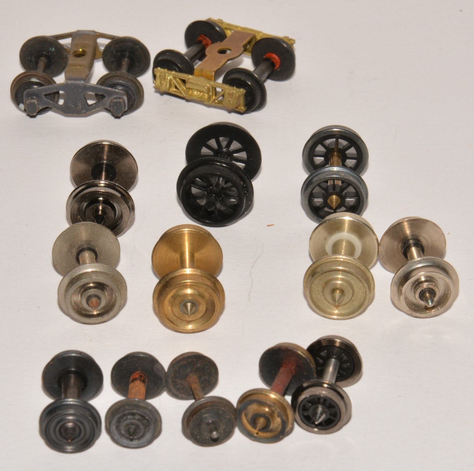
If you been modelling for some time you will most likely recall the good old days when rollingstock came with plastic wheelsets and your wagons didn’t roll all that well. Metal wheels mounted in delrin/acetal plastic side frames came along and improved things dramatically including highlighting where your layout was not level. It didn’t take long before most modellers changed out their plastic wheels for metal.

Modelling a 12 mm system, any wheelset was worth a pot gold and one took every opportunity to purchase them when they became available for future projects. After exchanging all my plastic wheelsets for metal, plus what I had for future projects and what I had been given, left me with a box of wheels no longer required. From time to time I would look at the box and ask myself “what are you going to do with them”. I know what Kerrie would say, “toss them” and few other kind words. The box would go back on the shelf until next time I was looking for something.

Some time back I added a wagon maintenance depot to the layout, to set the scene this gave me an opportunity to use a few on the wheelset.  


This is the back side of the scene, the detail of the workers etc. are out of view in this photo.

Recently I was researching a project and looking through various photos when the penny dropped what I could do with the plastic wheelsets. With the introduction of a wheel lathe at Redbank Workshops, the life of wheelset could be extended. This called for special wagons to carry wheels between workshops and maintenance depots. Over the years that followed lathes were installed in other workshops which lead to wagons being allocated to carry wheels around in their division. Over time older wagons were replaced with newer wagons, drawhook wagons were replaced with auto coupler wagons, all were converted from wagons no longer require for the purpose they were built for.    


The first wagons to be converted for this traffic were FJS, 4 wheeled open wagon to FJW and HS 8 wheeled open wagon to HSW. Plan P 94 gives a bit of information on the FJW wagons. Tare 5 T 9 Cwt and carry 11 T 11 Cwt. The wagon could carry 13 wheelsets with 33½” wheels, 9 on the floor and 4 on top. Wooden blocks were required for smaller wheelsets. The first FJW entered service in 1970 and the first FJWT (auto couplings) in 1971. I guess the FJWT were for the coal areas as most wagons had auto couples without buffers. 

FJWT Rockhampton

I cannot find much information on the HSW wagons. They were converted from HS wagons with a carrying capacity of 22 tons. The wagons had hook drawgear and were goods wagons restricted to 35 MPH or 60 KM/h. The HS class was unpopular with traffic staff due to the single door on each end. This limited there use as everything had to be man handled into the centre of the wagon or be lifted over the fixed sides. Shunters did not like the bogie, it was located right on the end of the wagon and had a guard around the leading end just a few inches above the rail. It was very easy to catch your feet under the guard, which earnt them the nick name as “toecutters”. Looking at the history of the wagon they entered service with a hopper type floor to discharge coke and concentrates for Mt Isa mines as the HVS class. The hoppers floors were replaced with a standard flat steel floor in the mid to late 1950’s and reclasses HS class. The guard may have acted as a plough to clear obstructions in front of the wheel to reduce the chance of derailments. The HSW lasted until the 1990’s. Some photos around this time show cover wagons on each end as the green light had been given to remover buffer of most wagons fitted with auto couplings. HSW would have been an interesting model to make with their fish belly underframes and outside brake gear. What put me off was their uneek bogie, I guess I could have used something similar, the object of the excise was to use up what I had in the draw.

HS Wagon in general traffic.

 HSW Wagon.

As I often put loads in wagons, I find the information on the carrying capacity of the FJW interesting. 13 wheelsets on a wagon that can carry 11½ tons, that makes a wheelset just under a ton, or around 18 Cwt an axle. I understood cast bogies were around 4 tons with the wheelsets being about 1 ton each. I had an H wagon looking for a load, the wagon didn’t have inside detail. I would think wheelsets were moved around the network before the introduction of the wheel wagons. An “H” wagon would be suitable for the job. H wagons can carry 12 tons plus an allowable 1½ ton overload, 13 wheelsets as above would give a full load within the carrying capacity. The wheelset would have been chocked with old sleepers making the loading process a bit messy and time consuming, with extra wheelsets moving over the network as a result of the lathes would be a good reason for a special wagon.  The “H” wagon would better suit my era. The black plastic wheelset were given a coat of burnt umber to give a more realistic used look. 


Around 1980, BSW wagons fitted with automatic and transition couplings started entering service. These wagons were red circle vehicles allowing them to travel at 80 km/h on express freight services. These wagons were converted from BLC box wagons. The plans show some wagons were built to carry 18 wheelsets with 915 mm diameter wheels and others to carry 19 wheelset with 850 mm diameter wheels. Early wagon for 850mm wheels converted retained their original number (31035, 31105), wagons converted in 1988 for 915mm wheels were allocated new numbers (36293, 36299, and 36300). All up eight wagons were converted over a number of years, the last be done in 1994.  Carrying capacity of the wagons were just 22 tons. The wagons remained in service until 2013.   


BSW 31035 Clapham. February 2000.

1991 the WHW wagons were introduced to the traffic converted from WHE grain wagons. Between 1991 and 1994, 11 wagons entered service. Two were scrapped in 2013. All retained their original numbers. In later years, the loading configuration was alerted on the wagons working out of Redbank. Wheelset were loaded across the wagon, I guess this was to allowing loading/unloading using forklifts.


 There were other wagons for wheelset/bogies including the PW for electric loco bogies, 6 were converted and one WHED class to carry bogies frames without wheels.  All were converted from WHE wagons.

To put my box of wheels to good use and to use other bits (bogies) in the cupboard, WHW wagons were built. The wagon were scratch built from styrene similar to other platform wagons on the layout. The plastic wheels are black and would not look right if placed on a wagon.


The wheelset were sprayed with a grey etch primer. The tyres were hand painted with “Model Color” gunmetal. Some weathering was added using earth colours and rust. Wheelsets are secured with web straps on the prototype, my straps are cut from a yellow plastic shopping bag, the bag was cut into 1 mm strips, and the strips were glued into place over the axles with super glue.  I use wheelsets of a different size and a mix of disc and spoked for most of my loads. Looking at later periods and certain areas, wheels going and coming from the coal fields etc., the wheelsets would all be the same type and diameter.                


Buffers were added to the models, plans for the wagon show buffers fitted. I would think given the period that WHW wagons entered service these wagon may of entered service without buffers.

I still have quite a few wheelsets in the box, HSW may find their way to the layout down the track.

Trust the article has inspired you to do something “out of the box” for your railway.

Acknowledgements.
QR Plan books.
Aurizon Wagon data information.

Arthur H.


Sunday, 3 May 2020

Dream Operations.

A railway that runs well is a joy to operate. There will always be a few derailments due to operator error, pulling the wrong points etc. From time to time wagons will derail at one set location on the layout or another wagon will keep derailing on a set of points. All of this can be fixed to give trouble free operation of your layout.


 Another point to consider is if you run operations to a time table, derailments will cause all sorts of havoc across the operations session to the point where the session is out of control and may not be all that much fun.   
To have a railway that run well, their need to be a good interface between the wheel and the rail. Good track is a must, ask they say in the prototype you require a good top and line. In other words, the top of the track most be in line, no dips, no kinks, twists or holes. I can hearing many of you saying, branch lines are far from it. That’s true, speed is low, often low axle loads, and a big plus is the rollingstock has spring. Our models don’t have springs to ride out the up and downs, thus good track is a must. Time taken to make sure your track is good and in gauge will repay you many times over with good operations.
Modelling H0n3½ there are many issues that impact on that good wheel rail interface.
Over years they has been various track systems used along with endless wheelset manufactures.
 At first, Tri-ang TT3 equipment was used. The manufacture made both set track and rollingstock. Gem produced flex track and points, Peco had their Wonderful Wagon series, all British manufactures for 12 mm gauge.


In Europe there was Bemo (Fine and course systems) and Pilz, in later years we have Tillig and Peco pitching at the meter gauge modelling. (Approx. 11.9 mm gauge), Shinohara is H0n3½ track for the Japanese market (approx. 12.3 mm gauge), this track system is no longer available. Some track systems are code 83 rail, PECO is code 75 and Shinohara was code 70. In Europe there has been a number of manufactures of rollingstock, Berliner Bahnen, Roco to make a couple. On top of this some TT models were produced in the US for local modellers.

Gem Track and Points.
 
Shinohara Track and Points.
Bottom – Peco Code 75, Middle – Shinohara Code 70, Top – Gem Code 83 Track
 Various manufactures have made wheelsets over the years, some plastic and other were metal of various types. Jackson, Wren, Peco TT, P.M.H, K&M made wheels for 12 mm and H0n3½ gauges, AR Kits, Steam Era Models. Now we have CGL, Caintode Flats Models, Southern Rail and Wuiske Models all producing wheelsets. Some wheelsets made for Shinohara track do not run through H0m points. Steam Era wheelset ran on most track systems I used over the years. The cost of them increased and troops stopped buying them. Production of 12 mm wheels no longer takes place, 9.5 mm disc wheels are still available. To add to this you will find the axle length will vary considerably between the manufactures. This prevents exchanging wheelsets between the various bogies.
 
When you look at the standards there is MOROP (European), NMRA, AMRA and British TT/TT3 or 3 mm. All are difference in various ways. I understand there was an H0n3½ standard developed in the 1960’s with AMRA and NMRA, but I was never aware of it. I started QR modelling in H0n3½ in 1973. At the time it was mainly British equipment used, some being Tri-ang. By today standards I fell the standard would not be that great anyhow. A paper written by Peter Knife “Modelling Australian HOn3½” for the Second Australian Narrow Gauge Convention held at Blackheath in 1998 cover standards and the industry at that time. http://www.minnipasiding.com.au/hon42.pdf
Today, in short we have track manufactures who do not make rollingstock and rollingstock manufactures who don’t make track.
I feel I cannot change track standards or any other standard for that natter, the most accessible track system today is the PECO H0m track which is the cheapest and most workable for the modeller. In recent year most manufactures producing rollingstock have adopted RP 25 contoured wheels. The theory is that the wheel is less likely to pick points and go around curves better. The standard states the wheels are best on track conforming to the limits of NMRA Standard S-3.2 and consistent with RP-10, RP-11 and RP-12.  At first we had RP 25/110 wheels, the tyre was wider than the prototype. To get a better looking wheel RP25/88 wheel was used.  The table below will give a overview of the difference between the two.
 
Tyre Width
Flange Width
Tread Width
Flange Depth
RP 25/110 wheel
.110”
(2.794 mm)
.030
(.762 mm)
.080
(2.032 mm)
.025
(.635 mm)
RP 25/88 wheel
.088”
(2.235 mm)
.025
(.635 mm)
.063
(1.6 mm)
.023
(.5842 mm)
 Yes, the RP25/88 wheel looks good, but you need a track system to the same standard. If the track is not the same standard, the wheels leave the rail and trend to fall into a hole at the vee on points. Some manufactures have back pedal a little and now use RP 25/99 wheels. Wider the wheel type, longer the axle, wider the bogie becomes. Wider bogies can take the true porotype look from the model.
This raises two questions, Question 1. Does my PECO H0m track conform to NMRA standards?. Track manufactures give you a gauge and not much more. The biggest issue is the clearances in the points around check rails. I’m aware some Peco track in other scales don’t meet these standards, my HO code 100 track has modifications to stop derailments. Question 2. How do RP25/88 wheelsets behave on the layout? Some run like a dream, faultless, can be pulled and pushed within in a string without any issues. Others turn into kangaroos at points, jumping up and down. Once a flange arrives on top of the rail, it’s any ones guess where the wheel will go, but mostly it finds the ballast. If the wagon is in a train being pulled, with a bit of luck at the next set of points the wheel will bounce back onto the rail. If you are pushing a wagon, once a flange arrives on top of the rail it all over. On closer inspection to find the cause, I observed there are differences in the flange shape on some wheelset said to be manufactured to the same standard. The back to back measurement could also very between different manufactures.
I have a test track, all wheelsets are tested before they hit the layout. The back to back is adjusted so the wheel run freely through the vee. Sitting on a chair, I place the board on the top of my legs, this allows me to alter the angle of the board and adjust the speed the wheels/bogies rolling through the points. Allowing the wheels to roll at a slow speed will show where the wheels meet resistance or climb onto the top of the rail head. 
Wheelsets that don’t run smoothly through the points have the back to back adjusted. I use two pullers to adjust the wheels on the axle.   
Hobby Tools Australia. This unit pulls the wheels out towards end of axle.
 
This gear puller can move the wheel in or out with adjustment of the centre screw. The centre screw was drilled out and a brass wheel bearing was inserted. I mainly use this tool for moving the wheel along the axle. I use the two to save adjusting the setting each time. (Lazy ??)
A good set of Vernier Callipers can be very helpful when adjusting wheelsets. The newer digital type make it much easier to read if you a bushie like me.  
 
 
Some wheels are gauged a recessed flange in the axle which prevents the wheels being pulled inwards. I’m very lucky I have a lathe, a small amount is taken off the back of the flange helps to achieve a wider back to back. I also do this with wheels with thicker flanges. Spinning a wheel in the lathe will also highlight if the wheel is square on the axle, I’m finding some insulated wheels have a wobble in them, thus they don’t run true and can pick the vee in the points at various times. Rolling the wheelset on a sheet of glass or a flat surface can achieve similar results. This could be the result of how you pull the wheelset out of the bogie, check before and pull on the non-insulated wheel. So be careful how you put the wheelset back into the bogie.  
 If you have plastic wheels there is nothing you can do to alter the back to back other than replacing the wheelset. Over a number of years, all my plastic wheels have been replaced with metal wheels. Don’t toss them in the bin, more on that down the track.  
 
The freer the wheels, the better with less friction. I have a modified H0 bearing tool to ream out the axle boxes on Delrin/Acetal plastic side frames.


The wheels need to turn freely will little to no side play in the axle.
The key point I try to achieve with wheelsets is reducing the resistance within the bogie and it interface with the track. Free rolling vehicles that run well on the track will give you less derailment and smoother operations overall. It will also show up how level your layout is.   
I try to have 30 foot wagons around 50 grams. Four wheeled wagons 25/30 grams appear to work OK, four wheeled wagons are trouble at the best of time if you want to push long strings. Some of the early carriage kits have a block of poxy for the roof, some are more than 3 times heavier than the rest of the kit, making the vehicle top heavy. I ream most of the poxy out using a dermal milling tool in a drill press.
 
Centre of gravity is very important to any railway, the lower the better. When adding weight to a vehicle I like to add plumber’s sheet lead to under the floor.
 
Coupled to this is the mounting position of the coupler. Most scratch build wagons I make my own coupler box reducing the side throw in the coupler. The back of the coupler socket is set level with the buffers heads. All wagons travel through cross overs without issues.
 Coupler heights can also differ, in the early days most kits were manufactured using the standard H0 Kadee coupler heights. This is higher than the QR  2’ 8” coupler height. To keep everything in prospective I mount couplers at 9.3 mm to the centre casting on the Kadee. Wuiske Models adopted a similar height for their RTR rollingstock. Southern Rail Models producing a dual position coupler box to cater for both by moving a spacer above or below the coupler shaft within the coupler box. For my money, wagons with standard H0 coupler height sit up much higher and makes the model look top heavy. As much as possible I try to keep the wagon/carriage floor and roof line at the correct height. The trip pin can hang low and catch on points etc., I bent them up a fraction. Australian Model Railway Magazine published an article “Coupling up in H0n3½” (April 2001). Stephen J. Colclough shares some hard earned lessons with coupling Queensland Railway HOn3½ models.
 
Building you own couple box into the wagon has some advantages, many older timber framed wagons have the bogie mounted on the end of the wagon. Standard Kadee coupler boxes fit between the wheels, but don’t allow them to swivel on small radius curves. Kadee makes a narrower # 262 box which can be purchased separate and are much better for the narrow gauge modeller. Building your own coupler box you can alter the shape of the yoke protruding out from the headstock. This can give extra support under the coupler shaft to prevent couples from sagging. It also allows you to reduce the cross movement within the box stopping couplings pushing outwards when pushing back.  
 

Most QR RTR rollingstock on the market today will run on PECO H0m track, radius of curves can be biggest issue, some locos may have issues on the points. If it is any comfort, the 6 wheeled DEL bogie caused many issues at first on the QR. I find PECO points can lose their gauge in the switch blades, I hold the toe of the switch hard up on the stock rail and with the other hand apply a small amount of pressure to the middle of the switch (curved closure rail), care is need not to apply to much pressure so that it pulls the rail out of the heel block.
 
 
Trust this helps you enjoy your railway more.
 
Arthur.